Home
/ 555 Timer Schematic Symbol - Inverted 555 Timer CircuitElectronics Project Circuts : The 555 timer ic is an integrated circuit (chip) used in a variety of timer, pulse generation, and oscillator applications.
555 Timer Schematic Symbol - Inverted 555 Timer CircuitElectronics Project Circuts : The 555 timer ic is an integrated circuit (chip) used in a variety of timer, pulse generation, and oscillator applications.
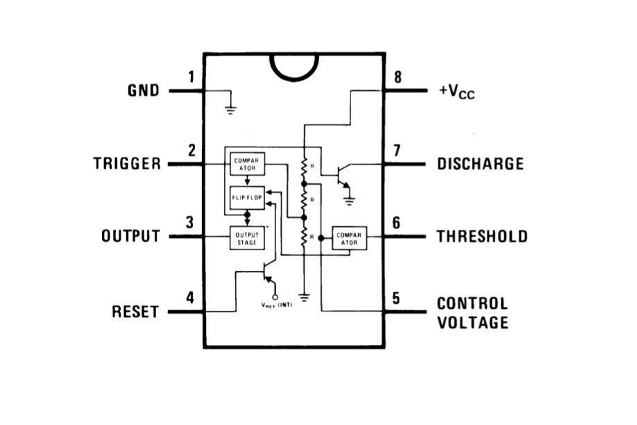
555 Timer Schematic Symbol - Inverted 555 Timer CircuitElectronics Project Circuts : The 555 timer ic is an integrated circuit (chip) used in a variety of timer, pulse generation, and oscillator applications.. Although a circuit common symbol is shown, the collector is not. Use this picture for wiring a center negative power supply. How do i draw this schematic on latex? In the schematic above, notice that the. 555 timer is an industrial standard ic existing from early days of ic.
The Three Fives Kit: A Discrete 555 Timer - RF Cafe from rfcafe.com The 555 timer can provide time delays ranging from several minutes for one cycle of operation to many thousands of cycles per second. Transistor q3 is actually connected as a diode with the collector not carrying current. 555 timer is an industrial standard ic existing from early days of ic. Usually used to create time delays. The 555 timer, designed by hans camenzind in 1971. And now a full schematic of the 555 timer oscillator with single step and free run option. The 555 timer was introduced over 40 years ago. You can watch the following video or read the written tutorial below.
Simple 555 timer circuits & projects.
When vcc > 9v, the base to emitter junction starts to zener and. It does not have pins 1 to 4 on one side and pins 5 building the circuit. Only attach an 1k resistor + led from pin 3 to ground. In the schematic above, notice that the threshold pin and. Basically, this means that you will have a continuous transition from a high voltage level (determined by and slightly. The 555 timer, designed by hans camenzind in 1971. The 555 timer is an integrated circuit, it is extremely versatile and can be used to build lots of different circuits. If you still need a detailed understanding of the 555 timer. The 555 timer was introduced over 40 years ago. Plug the 555 timer ic into the breadboard across the middle insulating channel. Its name is derived from three 5k ohm resistors,connected in series used in it.the timer ic can produce required waveform accurately. The first simply uses a normal 2n3904 garden variety transistor, and this works well when vcc < 9v. Due to its relative simplicity, ease of use and low cost it has been used in literally thousands of applications.
This tutorial provides sample circuits to set up a 555 timer in monostable, astable, and bistable modes as well as an in depth by wiring the 555 timer with resistors and capacitors in various ways, you can get it to operate in three different modes: Its name is derived from three 5k ohm resistors,connected in series used in it.the timer ic can produce required waveform accurately. It is a slave to timer a. None of the ic's pins will be shorted out because of. In the schematic above, notice that the threshold pin and.
Alternate Switching Relay Timer Circuit from 2.bp.blogspot.com It is a affordable, stable and user friendly ic in. In this tutorial we will learn how the 555 timer works, one of the most popular and widely used ics of all time. In astable mode, the output cycles on and off continuously. The 555 timer was introduced over 40 years ago. When vcc > 9v, the base to emitter junction starts to zener and. Its name is derived from three 5k ohm resistors,connected in series used in it.the timer ic can produce required waveform accurately. Its name is derived from three 5k ohm resistors ,connected in series used in it.the timer ic can produce 555 timer was first introduced by signetics corporation in 1971 as se555/ne555. Introduced in 1971 by the american company signetics, the 555 is.
The diagram below the 555 die photo and schematic below are interactive.
Above schematic diagram shows the 555 timer monostable multivibrator circuit. This article covers every basic aspect of 555 timer ic. Plug the 555 timer ic into the breadboard across the middle insulating channel. And now a full schematic of the 555 timer oscillator with single step and free run option. The 555 timer ic is an integrated circuit (chip) used in a variety of timer, pulse generation, and oscillator applications. Its name is derived from three 5k ohm resistors ,connected in series used in it.the timer ic can produce 555 timer was first introduced by signetics corporation in 1971 as se555/ne555. The schematic symbol for the 555 timer ic is not drawn to the layout of the physical 555 ic. 555 ic automatically switches back to stable state after some time, this time, for which the 555 stays in quasi stable state, is determined by the time constant of rc network in the circuit. In the schematic above, notice that the. It's a simple source of oscillating current that can power blinking leds, generate tones, and lots of other useful applications. Its name is derived from three 5k ohm resistors,connected in series used in it.the timer ic can produce required waveform accurately. 555 timer is an industrial standard ic existing from early days of ic. The first simply uses a normal 2n3904 garden variety transistor, and this works well when vcc < 9v.
Simple 555 timer circuits & projects. The basic 555 timer ic included in the chipkit™ starter kit is the ne555. Monostable mode is great for creating time. Transistor q3 is actually connected as a diode with the collector not carrying current. Outputs an oscillating pulse signal.
How to Read Electrical Schematics - Circuit Basics from www.circuitbasics.com The diagram below the 555 die photo and schematic below are interactive. There are several different part numbers that are 555 timers, and most of them are similar enough to ignore the differences, but check the data sheet for the particular limitations. Plug the 555 timer ic into the breadboard across the middle insulating channel. Basically, this means that you will have a continuous transition from a high voltage level (determined by and slightly. Usually used to create time delays. • in the time delay mode, the delay is controlled by • to understand how the capacitor is used in the 555 timer oscillator circuit, you must understand the basic charge and discharge cycles of the capacitor. This circuit generates a stable train of pulses. Due to its relative simplicity, ease of use and low cost it has been used in literally thousands of applications.
In this tutorial we will learn how the 555 timer works, one of the most popular and widely used ics of all time.
How do i draw this schematic on latex? You can watch the following video or read the written tutorial below. The 555 timer is an integrated circuit, it is extremely versatile and can be used to build lots of different circuits. The 555 timer is a simple integrated circuit that can be used to make many different electronic circuits. • in the time delay mode, the delay is controlled by • to understand how the capacitor is used in the 555 timer oscillator circuit, you must understand the basic charge and discharge cycles of the capacitor. Introduced in 1971 by the american company signetics, the 555 is. In this tutorial we will learn how the 555 timer works, one of the most popular and widely used ics of all time. Transistor q3 is actually connected as a diode with the collector not carrying current. The 555 timer changes its output depending on the state of two inputs. It does so thanks to feedback—the timing capacitor is connected to the trigger. This tutorial provides sample circuits to set up a 555 timer in monostable, astable, and bistable modes as well as an in depth by wiring the 555 timer with resistors and capacitors in various ways, you can get it to operate in three different modes: Derivatives provide two (556) or four (558) timing circuits in one package. The 555 timer can provide time delays ranging from several minutes for one cycle of operation to many thousands of cycles per second.
In astable mode, the output cycles on and off continuously 555 timer schematic. If you still need a detailed understanding of the 555 timer.